Introduction:
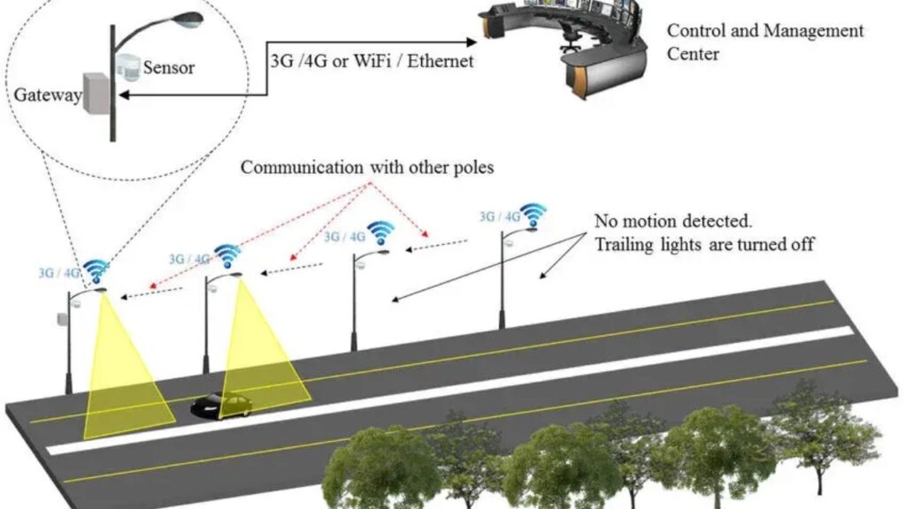
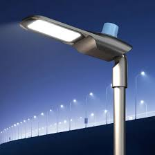
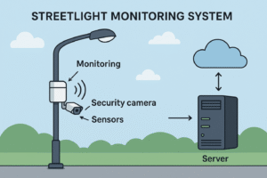
A street light monitoring system is designed to automate and monitor street lights for energy efficiency and maintenance. Conventional street lights consume unnecessary electricity when not optimized for real conditions. This project offers a smart solution by turning the lights on/off based on light intensity or a time schedule. This system enhances safety on the roads while reducing electricity costs for municipalities. It uses sensors to detect ambient light and microcontrollers to process data. The automatic operation reduces human effort to manually turn street lights on and off. It can detect failures, such as lights that do not turn on or off, and reports them remotely. This project combines IoT capabilities for remote monitoring and data analysis.
A street light monitoring system is designed to automate and monitor street lights for energy efficiency and maintenance. Conventional street lights consume unnecessary electricity when not optimized for real conditions. This project offers a smart solution by turning the lights on/off based on light intensity or a time schedule. This system enhances safety on the roads while reducing electricity costs for municipalities. It uses sensors to detect ambient light and microcontrollers to process data. The automatic operation reduces human effort to manually turn street lights on and off. It can detect failures, such as lights that do not turn on or off, and reports them remotely. This project combines IoT capabilities for remote monitoring and data analysis.
Hardware Components
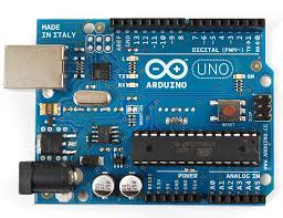
- Arduino Uno:Main controller that processes sensor data and controls outputs.
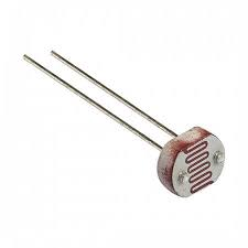
- LDR:Senses ambient light to determine day or night conditions.
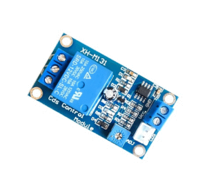
- Relay Module:Switches the streetlight ON or OFF based on microcontroller signals.
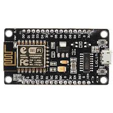
- ESP8266 WiFi Module:Enables wireless data transmission for monitoring the system remotely.
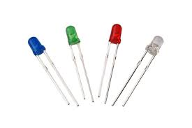
- LEDs:Act as model streetlights for testing the circuit on a small scale.
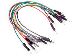
- Jumper wires:Provide electrical connections between components on the breadboard.
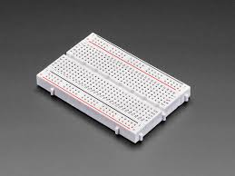
- Breadboard:Temporary platform for assembling and testing the circuit without soldering.
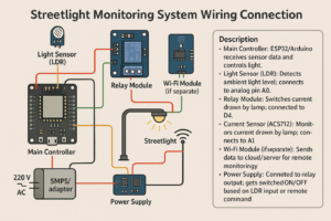
Wiring Connections:
- Connect the LDR in a voltage divider circuit to an analog pin (A0) of Arduino.
- Relay control pin connected to digital pin (D8) of Arduino.
- LEDs connected to relay outputs simulating streetlights.
- ESP8266 TX/RX connected to Arduino RX/TX (via voltage divider if needed).
- VCC and GND of all modules connected appropriately to 5V and GND rails.
Code:
// Pin Definitions
const int ldrPin = A0; // LDR connected to analog pin A0
const int relayPin = 8; // Relay control connected to digital pin 8
// Light threshold (adjust as needed)
const int threshold = 500; // Lower value: darker environment
void setup() {
pinMode(relayPin, OUTPUT);
digitalWrite(relayPin, LOW); // Start with lights OFF
Serial.begin(9600); // Serial for debugging / optional IoT
}
void loop() {
int ldrValue = analogRead(ldrPin);
Serial.print(“LDR Value: “);
Serial.println(ldrValue);
if (ldrValue < threshold) {
// It’s dark – turn ON streetlight
digitalWrite(relayPin, HIGH);
Serial.println(“Streetlight ON”);
} else {
// It’s bright – turn OFF streetlight
digitalWrite(relayPin, LOW);
Serial.println(“Streetlight OFF”);
}
delay(1000); // Read every second
}