Introduction:
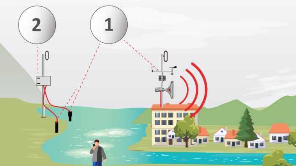
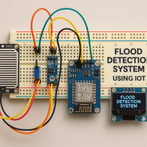
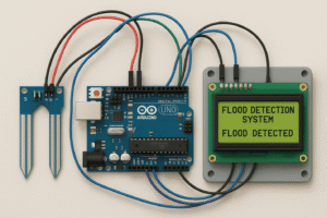
Floods are one of the most devastating natural disasters, causing immense damage to human life and property. Early warning systems can provide time to save people, allowing them to reach safe places or take preventive measures. A flood detection system uses sensors to detect rising water levels and alert authorities or residents. This system allows for continuous monitoring of water levels, providing real-time feedback. The goal of this project is to develop a low-cost and effective flood detection solution. It uses simple electronic components that are available to students and enthusiasts. An Arduino microcontroller acts as the brain of this system. An ultrasonic sensor measures the distance to the water surface. If the water level exceeds the safe limit, this system activates an alarm.
A buzzer and an LED provide visual and audible alerts. A GSM module can also be included for SMS notifications. This system is suitable for rivers, drainage systems, or areas affected by flooding. Through self-detection, it reduces the need for constant human monitoring. It also allows for integration with networks managing large natural disasters. This project demonstrates the practical use of embedded systems in environmental protection. It highlights the importance of combining hardware and software for real-world problems.
Hardware Components
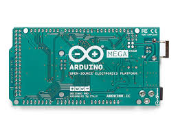
- Arduino Uno or Mega microcontroller:
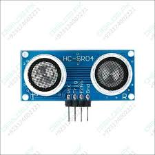
- Ultrasonic sensor (HC-SR04) for water level measurement:
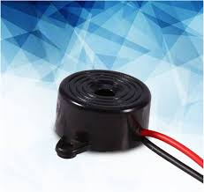
- Buzzer for audible alarm:
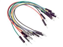
- Jumper wires:
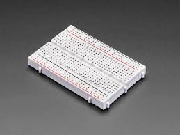
- Breadboard:
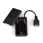
- Power supply (battery or USB):
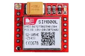
- (Optional) GSM module (e.g., SIM800L) for SMS alerts
Wiring Connections
- Connect VCC of HC-SR04 to 5V on Arduino, GND to GND
- HC-SR04 Trigger pin to Arduino digital pin 9, Echo pin to digital pin 10
- Connect Buzzer positive to Arduino pin 8, negative to GND
- Connect LED positive (with a 220Ω resistor) to Arduino pin 7, negative to GND
- Ensure all components share a common ground with the Arduino
- (Optional) For GSM, connect TX of GSM module to Arduino RX pin, RX to TX with appropriate logic level shifter
Code:
#define trigPin 9
#define echoPin 10
#define buzzer 8
#define led 7
void setup() {
pinMode(trigPin, OUTPUT);
pinMode(echoPin, INPUT);
pinMode(buzzer, OUTPUT);
pinMode(led, OUTPUT);
Serial.begin(9600);
}
void loop() {
long duration;
float distance;
digitalWrite(trigPin, LOW);
delayMicroseconds(2);
digitalWrite(trigPin, HIGH);
delayMicroseconds(10);
digitalWrite(trigPin, LOW);
duration = pulseIn(echoPin, HIGH);
distance = duration * 0.034 / 2;
Serial.print(“Distance: “);
Serial.println(distance);
if (distance < 20) { // threshold in cm
digitalWrite(buzzer, HIGH);
digitalWrite(led, HIGH);
} else {
digitalWrite(buzzer, LOW);
digitalWrite(led, LOW);
}
delay(500);
}