Introduction
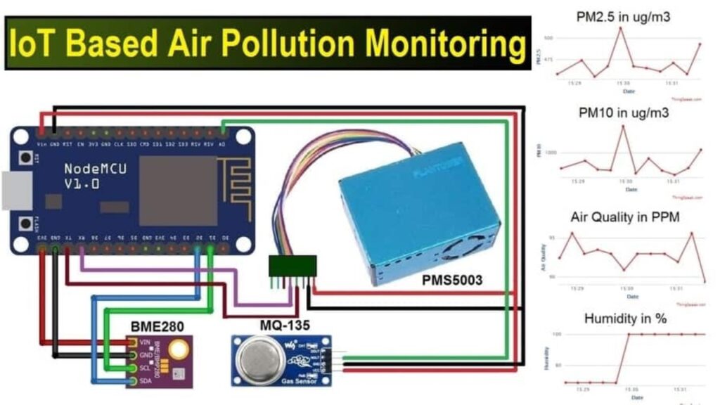
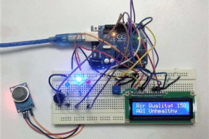
The air pollution monitoring system is an embedded system designed to identify and display the level of harmful gases and particles in the air. Air pollution has serious effects on health, especially in urban and industrial areas. This system helps monitor air quality in real-time in homes, schools, or public places. It uses gas sensors to detect pollutants such as CO, CO₂, NH₃, LPG, and smoke. A microcontroller (Arduino or NodeMCU) processes the sensor data. The system displays the data directly on an LCD screen or sends it to the cloud (for example, via Wi-Fi). Optional features include an alert system such as horns, LEDs, or even SMS/email notifications. This system can display temperature and humidity using DHT11 or DHT22 sensors. It is useful for educational projects, smart cities, and IoT enthusiasts. It helps with environmental awareness and early pollution control. This system is cost-effective and can be easily built with basic electronics knowledge. A mobile panel or a web dashboard can be included for better monitoring. You can combine this system with solar panels to make it eco-friendly. This project promotes the practical use of IoT to solve real-world problems. It can store data on platforms like Thing Speak, Blynk, or Firebase. It is an intelligent way to combat air pollution using technology.
Hardware Components (Written Form)
Component | Quantity | Description |
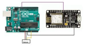
Arduino Uno / NodeMCU | 1 | Main microcontroller unit |
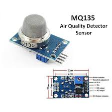
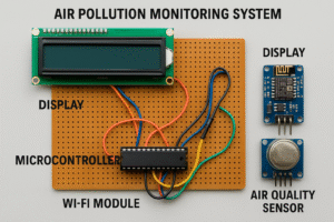
MQ135 Gas Sensor | 1 | Detects CO₂, NH₃, Benzene, and other gases |
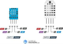
DHT11 / DHT22 Sensor | 1 | Measures temperature and humidity |
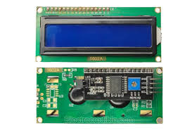
16×2 LCD Display (I2C) | 1 | Displays sensor data |
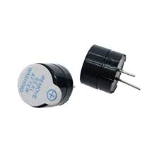
Buzzer (Optional) | 1 | Alerts for unsafe air quality |
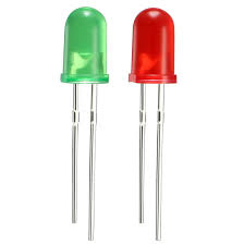
Red & Green LEDs | 2 | Air quality indicators |
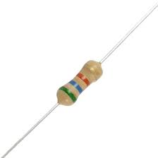
Resistors (220Ω) | 2–3 | For LEDs |
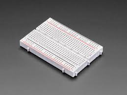
Breadboard | 1 | For easy prototyping |
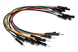
Jumper Wires | Several | For all connections |
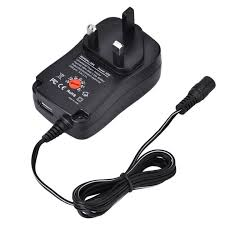
Power Supply (USB or 9V) | 1 | To power Arduino or NodeMCU |
I2C Module (for LCD) | 1 | Enables LCD control via I2C |
Wi-Fi (NodeMCU only) | – | For uploading data to IoT platforms |
Arduino Uno / NodeMCU:
MQ135 Gas Sensor:
|
DHT11 / DHT22 Sensor:
|
16×2 LCD Display (I2C):
|
Buzzer (Optional):
|
Red & Green LEDs:
|
Resistors (220Ω):
|
Breadboard:
|
Jumper Wires:
|
Power Supply (USB or 9V):
|
|
Wiring Components (Written Form)
🔸 MQ135 Gas Sensor to Arduino
- VCC→ Arduino 5V
- GND→ Arduino GND
- AO→ Arduino A0
🔸 DHT11/DHT22 Sensor
- VCC→ Arduino 5V
- GND→ Arduino GND
- DATA→ Arduino pin 2
🔸 LCD with I2C Module
- VCC→ Arduino 5V
- GND→ Arduino GND
- SDA→ Arduino A4
- SCL→ Arduino A5
🔸 Buzzer & LEDs
- Buzzer (+)→ Arduino pin 9
- Red LED (+)→ Arduino pin 10
- Green LED (+)→ Arduino pin 11
- All GNDs→ Arduino GND via resistors
Code:
Arduino Code (Air Pollution Monitoring System)
#include <LiquidCrystal_I2C.h>
#include <DHT.h>
#define DHTPIN 2 // DHT sensor pin
#define DHTTYPE DHT11 // or DHT22
#define BUZZER 9
#define RED_LED 10
#define GREEN_LED 11
#define GAS_SENSOR A0 // MQ135 analog pin
DHT dht(DHTPIN, DHTTYPE);
LiquidCrystal_I2C lcd(0x27, 16, 2); // I2C address
void setup() {
pinMode(BUZZER, OUTPUT);
pinMode(RED_LED, OUTPUT);
pinMode(GREEN_LED, OUTPUT);
lcd.begin();
lcd.backlight();
dht.begin();
Serial.begin(9600);
}
void loop() {
float gasValue = analogRead(GAS_SENSOR);
float temp = dht.readTemperature();
float hum = dht.readHumidity();
lcd.clear();
lcd.setCursor(0, 0);
lcd.print(“Gas: “);
lcd.print(gasValue);
lcd.setCursor(0, 1);
lcd.print(“T:”);
lcd.print(temp);
lcd.print(” H:”);
lcd.print(hum);
Serial.print(“Gas: “); Serial.print(gasValue);
Serial.print(” Temp: “); Serial.print(temp);
Serial.print(” Hum: “); Serial.println(hum);
if (gasValue > 300) {
digitalWrite(RED_LED, HIGH);
digitalWrite(GREEN_LED, LOW);
digitalWrite(BUZZER, HIGH);
} else {
digitalWrite(RED_LED, LOW);
digitalWrite(GREEN_LED, HIGH);
digitalWrite(BUZZER, LOW);
}
delay(2000);
}