
Introduction
The accident detection and prevention system for autonomous vehicles is an intelligent safety system designed to save lives. It uses vibration and motion sensors in the vehicle to detect accidents in real-time. When an accident is detected, it sends an emergency SMS that includes the location (GPS coordinates). This helps rescue teams or family members arrive quickly at the accident site. This system uses NodeMCU or Arduino UNO, along with GSM and GPS modules. The vibration sensors detect accidents or severe impacts. The GPS modules (such as the NEO-6M) provide the vehicle’s location in real-time. The GSM modules (SIM800L or SIM900A) send SMS text messages to a predefined number. This is a real-time IoT-based security solution for smart vehicles. The system can also alert nearby hospitals or emergency contacts. A buzzer or LED can be used for local alerts. This project is portable and suitable for vehicles, motorcycles, or school buses. It operates autonomously without the need for internet, only requiring GSM signal. It saves valuable time and increases survival opportunities in emergencies. Additional sensors (such as flame, tilt) can also be included for modern safety. This project helps reduce road deaths through technology.
.
🧰 Hardware Components (Written Form)
Component | Quantity | Description |
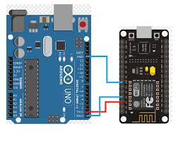
Arduino UNO / NodeMCU | 1 | Microcontroller (choose one) |
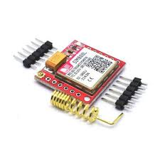
SIM800L / SIM900 GSM | 1 | To send emergency SMS |
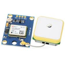
GPS Module (NEO-6M) | 1 | To get vehicle location |
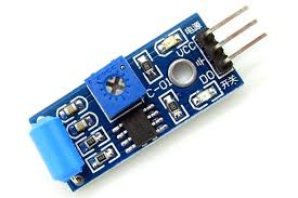
Vibration Sensor (SW-420) | 1 | Detects collision/impact |
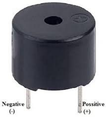
Buzzer (Optional) | 1 | Beeps when accident is detected |
LED (Optional) | 1 | Blinks during alert |
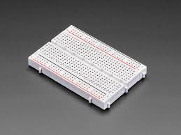
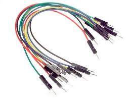
Breadboard + Jumper Wires | Several | For connections |
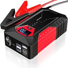
Power Bank or 12V Battery | 1 | To power system in vehicle |
Resistors (1kΩ) | 1–2 | For safety & voltage dividers (if needed) |
Arduino UNO / NodeMCU:
|
SIM800L / SIM900 GSM:
|
GPS Module (NEO-6M):
|
Vibration Sensor (SW-420):
‘ |
Buzzer (Optional):
|
Breadboard:
Jumper Wires:
|
Power Bank or 12V Battery:
|
Resistors (1kΩ):
|
🔌 Wiring Connections (Written Form)
🔸 Vibration Sensor (SW-420)
- VCC→ Arduino 5V
- GND→ GND
- DO→ Digital Pin D2
🔸 GPS Module (NEO-6M)
- VCC→ Arduino 3V or 5V
- GND→ GND
- TX→ Arduino RX (D0)
- RX→ Arduino TX (D1) (Use SoftwareSerial on other pins if needed)
🔸 GSM Module (SIM800L / SIM900)
- VCC→ External 4V Power Supply (GSM is sensitive!)
- GND→ Common GND
- TX→ Arduino D7
- RX→ Arduino D8
🔸 Buzzer / LED (Optional)
- +ve→ Digital Pin D3 / D4
- -ve→ GND


💻 Code (Arduino with GSM + GPS + Vibration)
#include <SoftwareSerial.h>
#include <TinyGPS++.h>
TinyGPSPlus gps;
SoftwareSerial gpsSerial(4, 3); // RX, TX for GPS
SoftwareSerial gsmSerial(7, 8); // RX, TX for GSM
const int vibrationPin = 2;
const int buzzerPin = 5;
bool accidentDetected = false;
void setup() {
Serial.begin(9600);
gpsSerial.begin(9600);
gsmSerial.begin(9600);
pinMode(vibrationPin, INPUT);
pinMode(buzzerPin, OUTPUT);
digitalWrite(buzzerPin, LOW);
delay(2000);
gsmSerial.println(“AT”);
delay(1000);
gsmSerial.println(“AT+CMGF=1”); // Text mode
delay(1000);
}
void loop() {
while (gpsSerial.available()) {
gps.encode(gpsSerial.read());
}
int vibrationState = digitalRead(vibrationPin);
if (vibrationState == HIGH && !accidentDetected) {
accidentDetected = true;
digitalWrite(buzzerPin, HIGH);
delay(1000);
digitalWrite(buzzerPin, LOW);
float lat = gps.location.lat();
float lng = gps.location.lng();
sendSMS(lat, lng);
}
}
void sendSMS(float lat, float lng) {
gsmSerial.println(“AT+CMGF=1”);
delay(500);
gsmSerial.println(“AT+CMGS=\”+911234567890\””); // Replace with your number
delay(500);
gsmSerial.print(“⚠️ Accident Detected!\nLocation:\n”);
gsmSerial.print(“Latitude: “);
gsmSerial.println(lat, 6);
gsmSerial.print(“Longitude: “);
gsmSerial.println(lng, 6);
delay(500);
gsmSerial.write(26); // End SMS with Ctrl+Z
delay(2000);
}